Home / About BEVI / Knowledge bank / General technical information on electric motors
Three phase single speed motors can normally be connected for two different voltage ranges.
This is because the three phases of the stator winding can be connected in two ways: connection in star (higher voltage), or delta (lower voltage) with a ratio of √3. The lowest voltage is used when the motor is connected in D and the highest voltage when the motor is connected in Y. The voltage at Y = √3 × the voltage at D.
Example
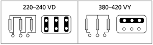
a) 220-240 VD/380-420 VY - may be labelled 230/400 V (standard for motors 3 kW and smaller). Suitable for direct o line (DOL) starting on 380-420 V supplies.
Example
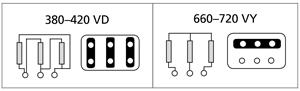
b) 380-420 VD/660-720 VY - may be labelled 400 VD (standard for motors 4 kW and larger). Suitable for Star/Delta starting on 380-420 V supplies or direct on line starting on 660-720 V supplies.
The mains voltage can vary ± 10% at 400 V or ± 5% for wide voltage range rated motors without needing the motor's nominal power to change. Note that the efficiency is set at 230 V and 400 V values, respectively.
Contact
Pontus Adolfsson, Product manager electric motors:
The motors are balanced with a half key. Special degrees of balancing are available on request.
Fuses do not provide protection for a motor, but are only protection against short circuits in the circuit.
Raised motor temperature, due to overload or failure of a phase, is prevented by a motor protective switch. The current, to which the thermal overload protection is to be set, is indicated on the motor's nameplate. In some cases, an ordinary motor protective switch is not sufficient protection. This applies especially to more difficult operating conditions, e.g. starting of equipment with high moment of inertia, when using frequency inverters and operating conditions with large differences in cooling temperature. In these cases, thermal protectors (eg, clixon) or thermistors in the windings can be used.
Thermal protectors are usually mounted in the motor winding. When a certain temperature is reached, the thermal protectors break an electrical circuit, e.g. the supply voltage to a contactor that switches off the motor. The breaking contact is a temperature sensitive bimetallic spring. BEVI can retrofit thermal contacts in all motor sizes.
Thermistors are used for temperature monitoring.
The protection unit consists of the thermistors that can be mounted in the windings and a trigger device. The thermistors are temperature sensitive resistors which at a certain temperature change the resistance considerably. This is sensed by the trigger device which in turn e.g. switches the supply voltage off to the main contactor. BEVI's IE3 motors have thermistors as standard. BEVI can also retrofit thermistors in all motor sizes.
As standard, the fan and cowl is fitted at the non-drive end (cooling form IC 411). Other cooling methods can be supplied e.g. a separately driven cooling fan which is often used with inverter drives.
Motors used in conditions of wide temperature variations or extreme climatic conditions can be damaged by condensation and dampness in the windings. In motors fitted with heaters, the windings are heated to a few degrees above the ambient temperature when the engine is switched off. This is enough to prevent condensation. The standby heater must be switched off when the engine is running.
Smaller motors can also be heated by applying a low voltage across the motor winding. The voltage should be 5-10% of the rated voltage over two phases.
BEVI can fit heaters to all motor sizes on request.
The motors are manufactured with different quality on the insulation material. The insulation materials are divided into different classes which are indicated by a letter, e.g. B or F. The insulation class indicates the upper temperature limit that the insulation material can withstand. Ambient temperature, permissible temperature rise and the temperature reserve are factors that determine how much a motor can be loaded.
The rated power of a motor is normally specified for an ambient temperature of + 40°C. If the ambient temperature is higher, the output power must be reduced.
BEVI's motors are normally wound with class F material but can be ordered with other materials, e.g. our wood dryer motors are wound with class H material.
Ambient temperature (°C)
Permissible temperature rise (°C)
Temperature reserve (°C)
Max temperature (°C)
The motor duty type is indicated by one of the designations S1 – S9. S1 is the normal operation after which the rated power of the motor is indicated. However, in certain operations the rated power of the motor can be increased. Depending on how the load and thus the output power of the motor vary with time, different duty types are given below. The rated power for each type of operation is determined by a load test, which the motor must pass without exceeding the temperature limits set in IEC 60034-1: 2017.
For duty type S2, the designation must be followed by the length of the load period. In the operating modes S3 and S6, the designation must be followed by an intermittent factor. Example: S2 60 min, S3 25%, S6 40% . At duties S4, S5, S7, S8, S9, designations must be followed by the moment of inertia etc.
Correct protection class is a prerequisite for a motor to be able to work safely for a long time in tough duty and challenging atmosphere. Motors are produced in degree of protection IP55 as standard, but are also available to other standards.
The motor construction, power rating and mounting dimensions meet the requirements of the international standards listed below.
Standard
Standard on efficiency measurement methods
BEVI's Knowledge bank collects information about our areas of expertise, electric drive systems and power generation.
BEVI is one of the Nordic region's largest companies in the field of electric drive systems and power generation.
We offer a comprehensive range of electric motors, transmission devices, power electronics, coil winding material, starter equipment and perform services of electrical machines.
BEVI AB (headquarters)
Tel: +46 499-271 00
Mail: info@bevi.se
Denmark / Export: bevi@bevi.com
Bevivägen 1, 384 30, Blomstermåla, Sweden


© BEVI AB 2024


